Modbus Protocol and Common Tools
The Modbus protocol is a communication protocol commonly used in the fields of industrial automation and the Internet of Things (IoT); the following is a detailed introduction to the Modbus protocol.
I. Overview
The Modbus protocol was originally developed by Modicon (now part of Schneider Electric) in 1979 to enable communication between automation devices. It has become an industry standard for communication protocols in the industrial sector and is widely used to connect industrial electronic devices.

II. Key Features
1. Simplicity: The Modbus protocol employs a simple communication format that is easy to understand and implement.
2. Flexibility: It supports various physical layers and transmission media—including serial interfaces (such as RS-232, RS-485, and RS-422) and Ethernet—allowing it to adapt to diverse communication requirements.
3. Scalability: The protocol supports master-slave architectures and multipoint communication, enabling easy expansion to multiple devices.
4. Openness: As an open protocol, it can be utilized and implemented by various manufacturers, fostering its widespread adoption in the field of industrial automation.
5. Reliability: The Modbus protocol offers robust fault tolerance and reliability, making it suitable for data communication and control in industrial environments.
III. Working Principle
The Modbus protocol employs a master-slave communication technique, in which the master device actively polls and operates the slave devices. The master device (such as an industrial PC or industrial controller) initiates each interaction, while slave devices (such as PLCs or sensors) receive data from the master and respond accordingly. During communication, the master sends a request and the slave replies; when the master is not transmitting, there is no data traffic on the bus. Slave devices do not initiate messages to the master; they only respond to requests sent by the master.
IV. Classification of Agreements
The Modbus protocol has various versions and variants designed to accommodate different communication requirements and transmission media. The most common ones include:
1. Modbus ASCII: When a device is configured to communicate via Modbus serial lines using ASCII mode, each 8-bit byte in the message is transmitted as two ASCII characters. This mode is less efficient than Modbus RTU because it requires two characters for every byte.
2. Modbus RTU: A compact binary data representation method. By combining binary encoding with CRC error checking, Modbus RTU is well-suited for industrial applications and offers more efficient transmission compared to ASCII-based alternatives.
3. Modbus TCP: An implementation of Modbus designed to operate over TCP/IP networks, enabling the transmission of Modbus ASCII/RTU protocols across TCP/IP-based infrastructure. It encapsulates Modbus messages within TCP/IP frames, thereby facilitating Modbus protocol communication over Ethernet.
V. Modbus RTU Frame Structure
Modbus RTU (Remote Terminal Unit) is a variant of the Modbus communication protocol used for serial communication. It is a common communication protocol for industrial control systems, typically employed to collect sensor data, control actuators, and monitor equipment status.
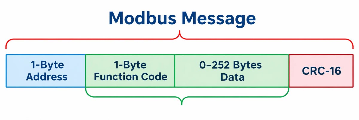
Address: The valid range is 0–247. A value of 0 indicates a broadcast message from the master station; values of 1–247 indicate either a request from the master station or a response from a slave station.
Function Code: This represents the command—specifically, the operation the master station is performing on the slave station (such as a read or write).
Data: The data field; the content differs between master request messages and slave response messages. Consequently, if capturing bus traffic, the data field is used to distinguish between a master request and a slave response.
CRC Check: Uses CRC16 (16-bit Cyclic Redundancy Check). The maximum total length of a Modbus RTU frame is 256 bytes (meaning the data portion can contain up to 252 bytes).
VI. Modbus TCP Frame Structure
A Modbus TCP data frame consists of two parts—MBAP and PDU—as shown in the figure below.
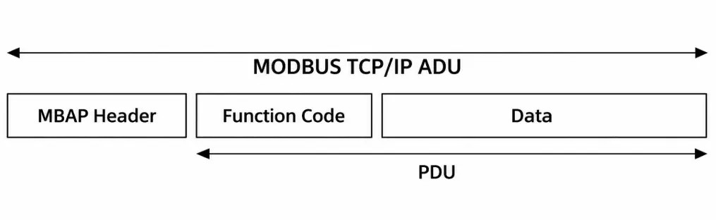
MBAP (Message Header)
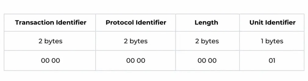
(1) Transaction Identifier: Can be interpreted as a message sequence number; the identifier increments by one each time the client sends data. The server returns this value unchanged upon receipt.
(2) Protocol Identifier: "00 00" represents the TCP protocol.
(3) Length: Indicates the length of the data following the Unit Identifier. For example, "00 06" indicates that 0x06 bytes of data follow.
(4) Unit Identifier: Equivalent to the device address. Typically set to 01.
PDU (Frame Structure)
PDU = Function Code + Data.

Function code:
(1) There are four types of Modbus data objects: coils, discrete inputs, input registers, and holding registers.
Coils: Equivalent to switches; they are readable and writable in Modbus, with data values of only 00 or 01.
Discrete inputs: Input bits or switch-type signals; they are read-only in Modbus.
Input registers: Registers that can only be modified via analog input channels; they are read-only in Modbus.
Holding registers: Registers used for analog signal output; they are readable and writable in Modbus.
(2) Depending on the object type, Modbus function codes include:
0x01: Read coils
0x05: Write single coil
0x0F: Write multiple coils
0x02: Read discrete inputs
0x04: Read input registers
0x03: Read holding registers
0x06: Write single holding register
0x10: Write multiple holding registers
VI. Common Modbus Tools
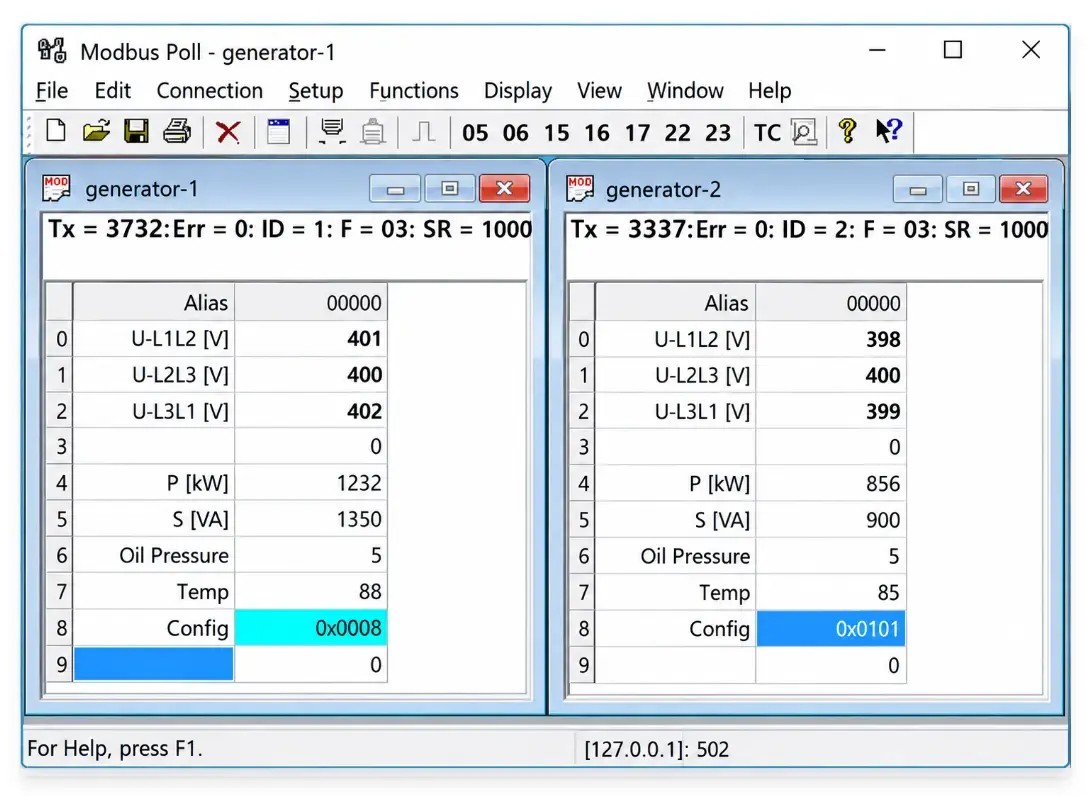
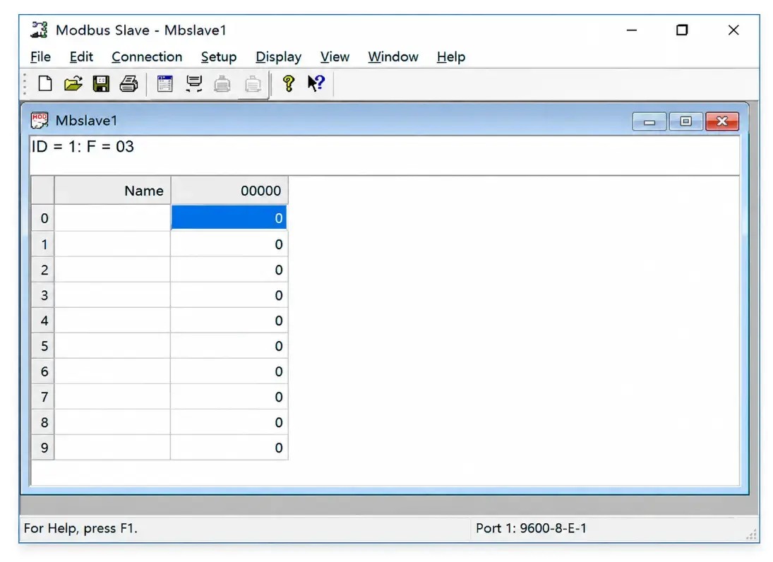
Modbus Poll and Modbus Slave are the most widely used and powerful tools available. Modbus Poll can simulate a master device in both RTU and TCP modes, while Modbus Slave can simulate a slave device in both RTU and TCP modes. They are excellent aids for understanding and developing the protocol.
Modbus Poll is shown below:
The Modbus slave is as follows:

Share




Leave a Message
Your email address will not be published.
Posts



Products